How do I capture an analog video signal with an oscilloscope?
When I was a child, my DVD was connected to the TV through several round plugs, and the plugs were color-coded. Now that the DVD has almost disappeared, the plugs on the TV still exist, and today we will reveal these plugs.
Which plugs the DVD is connected to is actually an audio and video transmission interface. Thanks to this transmission interface, we can see a variety of videos on the TV. With the continuous development of technology and information technology, there are more and more types of video information transmission. Let's take a look at the current mainstream video interface classifications on the market.
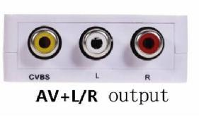
First, CVBS (also called RCA video or AV interface)
The CVBS Chinese name is a composite synchronous video broadcast signal, which is a widely used standard and the earliest interface for video transmission. It transmits data in analog waveforms, enabling separate transmission of audio and video, avoiding image degradation due to audio/video mixing interference. Since the interface transmission is a mixed luminance/chrominance signal, the display device needs to separately decode the signal light/color to be imaged, thereby causing loss of color signals and affecting image quality. Even so, CVBS still has a certain vitality.
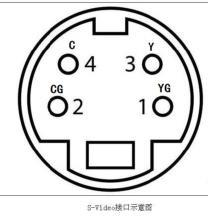
Second, S-Video (S video)
S-Video is also called two-component video interface, which means that the video signal is transmitted separately, that is, the luminance signal and the chrominance signal are separated on the basis of CVBS, and transmitted in different channels, so that the image is not required to be bright. The chrominance is separated and decoded, which largely avoids image distortion caused by signal crosstalk in the video device and improves the sharpness of the image. Currently S-Video is also a video interface commonly used.
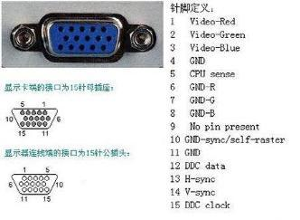
Third, VGA
The VGA interface adopts the 15-pin connection mode. The working principle is that the image signal stored in the data format in the memory memory is analog-modulated into an analog high-frequency signal in the RAMDAC, and then output to the plasma imaging, so that the input terminal does not have to be like other video signals. After the decoding circuit processing, the video transmission process of VGA is the shortest, so VGA has many advantages, such as no crosstalk and no circuit synthesis separation loss.
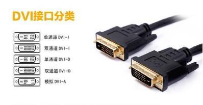
Fourth, DVI
The DVI interface is mainly used to connect to a computer graphics card with digital display output function to display the RGB signal of the computer. The DVI digital terminal is better than the standard VGA terminal. The digital interface ensures that all content is transmitted in digital format, ensuring data integrity during the host-to-monitor transmission process, resulting in clearer images.
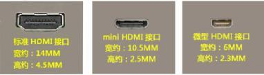
Five, HDMI
HDMI is based on DVI and can be seen as a reinforcement and extension of DVI. HDMI can transmit uncompressed high-resolution video and multi-channel audio data in digital form while maintaining high quality. It supports all ATSCHDTV standards, does not support high-definition 1080p resolution, and can support DVDAudio, etc. Digital audio format. HDMI is smaller and transmits both audio and video signals, and the cable has essentially no length limitations.
From the above video interface classification, we know that the transmission of video has analog and digital. If it is a digital transmission, the quality of the image can be guaranteed. However, there are still many analog signals transmitted on the market, so the measurement and analysis of analog signals is still very important and indispensable. Analog video signals support three formats: NTSC, PAL, SECAM.
The ZDS series oscilloscopes are equipped with a video trigger function that analyzes the above mentioned video signals.
l oscilloscope video trigger
Click the oscilloscope [Trigger] button to find the trigger mode. After selecting the video trigger mode, we can see the content selected by the video format and select the corresponding video format.
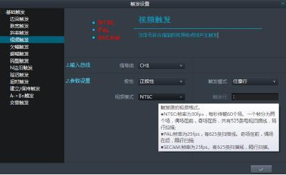
l trigger mode selection
After selecting the video trigger, you can select the trigger mode to trigger the data signal you want to see. At present, the remote oscilloscope supports 5 modes in any row, specified row, arbitrary field, even field, and odd field.
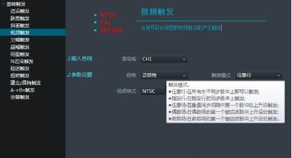
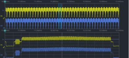
For example, let's set the trigger mode to the specified line trigger. The line setting range can be from 1 to 525. Set it to 400, adjust the hour base, and amplify the waveform to clearly see the waveform of the stable trigger. Trigger for line 400, the waveform is shown below.
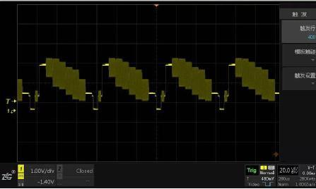
l waveform record analysis
The video signal is a continuous analog waveform. In order to fully analyze the waveform, we need to record the waveform and analyze it. At this time, the oscilloscope must have enough memory depth to see the details of the amplification after recording the waveform, as shown in the following figure.

We have artificial putting green grass surfaces designed for backyard putting greens that have the best ball roll available and golf course greens that will catch a shot from more than 200 yards out. For the golfer looking for a backyard putting green solution for their home, our golf artificial grass come built to last without the maintenance of a real grass green. Our artificial grass putting greens are the surface of choice all over the world. Our artificial grass turfs are designed to help you conserve energy, time, and water – in equal measure and of course money.
Golf Artificial Grass,Golf Putting Grass,Artificial Turf For Golf,Golf Astro Turf
JIANGSU WMGRASS CO., LTD. , https://www.wmgrasslawns.com