Design of smart home data acquisition card based on MB90F462
1 system structure and function overview
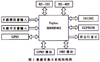
According to the characteristics of the online devices of the smart home system and the need for convenient control, the data acquisition card should have sufficient input and output interfaces and remote communication functions. The system structure of the data acquisition card based on MB90F462 is shown in Figure 1. The system can be divided into the following modules according to functions: 8 analog inputs; 8 digital inputs; GSM SMS data transmission; RS-232, RS-485 communication; GPRS data transmission; real-time clock; status indication; EEPROM data storage .
2.1 signal input module
In the smart home system, the data information to be collected includes air temperature, humidity, lighting adjustment and alarm information such as water, electricity, gas, smoke, fire, etc. According to the nature of the signal, it can be divided into analog data and digital data. . The data acquisition card supports input levels of 5V, 3.3V, RS-232 and RS-485.
The MB90F462 has 8 channels of 8/10-bit precision selectable A/D channels for analog signals from 8 sensors. For information such as temperature, humidity, light, and water flow, the real-time data of the device can be collected to the management center through the A/D channel through the corresponding sensor. Because the amount of data in the system is not large, the software design uses the way of query to check the sampling completion flag of each A/D, and reads the data into the computer of the management center. The registers that need to be set for A/D sampling include: ADER, ADCS1, ADCS0, ADCR1, and ADCR0. There are four selectable modes for A/D conversion: single-step conversion mode 1 (repetitive activation is allowed at runtime), single-step conversion mode 2 (repetitive activation is not allowed during operation), continuous conversion mode (repeated activation is not allowed during operation), Stop conversion mode (repeated activation is not allowed during runtime).
For the device's alarm information and some special switching, the digital input signal is triggered or pulse counted by the MB90F462's 8 external interrupts. Since the external interrupt and the GPIO pin are multiplexed, the corresponding pin must be set as an input when using an external interrupt. Each of the two external interrupts shares an interrupt control register. The registers that need to be set when using an external interrupt are ICRXX, ENIR, ELVR, and EIRR. The trigger signal level of the interrupt signal can be high level, low level, rising edge or falling edge. Clear the flag bit before using the external interrupt and after the interrupt processing is completed.
2.2 short message communication module
In order to serve users more conveniently, the smart home system uses GSM short message (SMS) service to realize remote alarm and remote control functions. Users can monitor the real-time status and alarm information of home devices through personal mobile phones, and also send short messages. The message remotely controls the switch of a device. SIEMENS' GSM wireless module TC35 has four data transmission functions: reliable data, voice, short message service and fax. The module's operating voltage is 3.3 ~ 5.5v, can work in 900MHz and 1800MHz two bands, the power consumption of the band is 2W (900MHz) and 1W (1800MHz). The data interface of the TC35 uses serial asynchronous transceiver, conforms to the ITU-T RS-232 interface circuit standard, and operates at CMOS level. Data interface configuration: 8-bit data bit, 1-bit stop bit, no parity bit, can run at baud rate from 300bps to 115Kbps, and the supported auto-baud rate is 4.8~115Kbps (14.4Kbps and 28. Except 8Kbps).
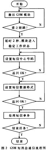
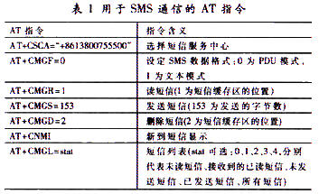
Before the short message communication, the GSM module is activated by outputting a voltage falling edge on the /IGT pin. After the module is stable, the SMS service center number and data format are set, and the operations of sending, receiving, deleting, and querying the short message are performed. The short message program design flow of GSM is shown in Figure 2. The AT commands for SMS communication are shown in Table 1.
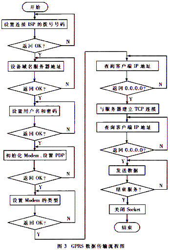
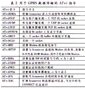
Compared with traditional GSM, GPRS communication is characterized by terminal mobility, short access time, fast transmission speed, flow rate, access to the Internet, and online. The GPRS network uses the TCP/IP protocol stack for networking, which can achieve seamless connection with the Internet network, but the data format should conform to the data packet format of the TCP/IP protocol stack during transmission. In order to realize point-to-point communication, the GPRS network uses the PPP protocol on the data link layer and serial port communication on the physical layer. Therefore, when implementing a GPRS-based data transmission system, data needs to be packaged, and the PPP protocol needs to be implemented on the data link layer. The flow of GPRS remote data transmission based on TCP/IP dedicated module is shown in Figure 3.
In order to manage each user's data reasonably and effectively, especially some alarm data, the real-time time of its occurrence should be recorded. The data acquisition card adopts a high-performance, low-power, real-time clock with RAM DS1302 introduced by DALLAS, USA, which can time the year, month, day, sun, hour, minute and second, with leap year compensation. Function; DS1302 and CPU synchronous serial communication, the interface only needs three lines: /RST, I/O, SCLK; can read and write 1 byte data or 31 bytes of string at a time; there are seven data registers, namely Second, minute, hour, date, month, week, and year registers; the address of the command word is from 80H to 8DH, the odd number is read, and the even number is write; one clock cycle begins with a falling edge and ends with a rising edge; when data is written, The data must remain valid during the rising edge of the clock. When the data is read, the data is valid during the falling edge of the clock; if the RST input is low, all data transfers are aborted and the I/O is high impedance; data input/output The timing is to first write a byte of the command byte (read or write), followed by 8 clock cycles to read / write a byte of data.
Although the power consumption of the DS1302 is small, if you want to ensure the clock is normal for a long time, it is best to use a small rechargeable battery or a super capacitor of 0.1F or more as the backup power supply. If the power-off time is short, it can be replaced by a common electrolytic capacitor with less leakage. The DS1302 must be initialized after the first power-up, and then the time can be adjusted in the normal way.
In addition, the system is also equipped with RS-232, RS-485 interface and EEPROM data memory, which is convenient for connection with other devices and realizes power-down data protection.
3 Accemic MDE debugging
Accemic MDE is the preferred tool on the market to debug Fujitsu 16LX series microcontrollers without emulators. The monitoring core runs in parallel with the application, so it is important to understand how the monitoring core works. Commissioning with Accemic MDE should be carried out in exactly the following steps:
(1) Connect the hardware (do not connect to the power supply) before starting Accemic.
(a) Set MB90F462 to the programmed state, that is, MD0, MD1, MD2, P00, and P01 are set to ON (=0), OFF (=1), OFF, ON, and ON, respectively.
(b) Connect the Bootloader-UART of the target board to the COM port of the PC with a serial cable (for the MB90460 series, UART0 is the Bootloader-UART).
(c) Power up the target board.
(2) Start the Accemic debugging environment
(a) Open the preference│systerm menu and set the CPU type, package type, working clock, multiplier, communication baud rate, reset line and COM port number.
(b) Press the "Download Monitor" button to import the monitoring kernel;
(c) Put the target system in the reset state and switch the MCU to the working state, that is, MD0, MD1, MD2, P00, and P01 are set to OFF, OFF, ON, X, and X, respectively.
(d) Exit the reset state, at which point the target system can be accessed through the monitoring kernel.
(e) Press the "Connect" button to start the connection debugging.
(3) Aecemic MDE debugging considerations
(a) Add the file "monitor.asm" located in the installation directory C:\programs\AccemicMDE\include of Accemic MDE to the user project before debugging; if you want to use the target information function, include "monitor." in the application. h" file (in the same directory as monitor.asm).
(b) If the Bootloader-UART does not use an external clock, do not use the function to change the PLL clock register. The PLL clock can be corrected by the setting in "start.asm" to ensure that the setting of CLOCKSPEED is NOCLOCK.
(c) The bootloader-UART interrupt level and the bootloader-UART register settings cannot be changed during debugging. Note that the bootloader-UART interrupt level should not be overwritten in the file "vectors.c".
(d) If you want to use the watchdog timer, you need to enable the Accemic MDE's watchdog timer auto-update function, that is, call the acc_WatchdogEnable() function in the program.
(e) In order to enable Monitor to enter the breakpoint in the interrupt service routine, two conditions must be met: one is to allow interrupt in the program, that is, the _EI() function is called; the other is that the interrupt service program has a higher interrupt level. 7 (because the interrupt level of the Bootloader-UART is 7).
(f) The MB90F462 has two UARTs, of which UART0 is BootloaderUart for in-circuit debugging and programming, or it can be multiplexed with the user program. When multiplexing, you need to call the function acc_KernelUART(1) defined in Accemic MDE. The default value of the parameter is 1, indicating that UART0 is used as normal user program communication; the default value of the parameter is 0, indicating that UART0 is used as the debug interface, which is not used in the user program. This function does not need to be called when going to UART0.
In summary, the data acquisition card provides 8 analog inputs and 8 digital input interfaces, and has two RS-232 interfaces, supporting RS-485, RS-232, 3.3V, 5V and other input power. Level, can realize on-site data acquisition and remote transmission, remote communication and transmission methods are GPRS and SMS; and remote switch control can be implemented on field devices. The data acquisition card transmission and protocol conversion are transparent, easy to use and reliable, and equipped with system configuration and maintenance interface to facilitate on-site maintenance, and can be widely applied to remote monitoring, remote meter data reading and other occasions.
private label collagen Eye Cream ,30 years experience guangzhou cosmetics factory supply ,OEM/ODM service is welcomed .
Guangzhou Athena Cosmetics Manufacturing Co.,Ltd is a subsidiary of YALAN international group which is located in Guangzhou,china.it is the production center of YALAN international group branding products,specialized in the development and production if cosmetics.ATHENA is qualified for import and export.
controls the quality in full accordance with GMP, ISO9001 quality system good manufacturing practice for cosmetics and key points of cosmetic production licence inspection.
collagen crystal eye mask, 24k gold collagen mask,private label collagen eye mask,anti-aging crystal collagen gold eye mask
Athena(Guangzhou) Cosmetics Manufacturer Co., Ltd , https://www.ydgzathenaskincare.com