Further analysis 5.7 overall machine debugging
The overall commissioning of the machine is the same as the commissioning of each unit. The key is the selection of the reference. Different models have different baselines, but only one absolute baseline. Monochrome or semi-satellite type presses generally use an impression cylinder. The group-type printers generally use register rollers. Regardless of which is the absolute benchmark, just make sure you can not adjust down (which itself must be in good working condition). After selecting the absolute reference of the machine, select the relative reference based on the relationship of the drive chain. With benchmarks and relative benchmarks, adjustments can be made in an orderly manner, as shown in Figure 5.17.
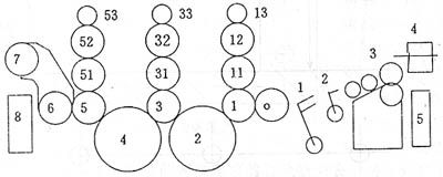 Figure 5.17
 The figure above is a schematic of a tuning reference. O is the absolute reference of the complete machine, l, 2... In turn are the first relative reference, the second relative reference of the complete machine, ...11,12,13 are the first relative reference of the printing unit with respect to the impression cylinder, the first Second relative to the benchmark, ..., other units and so on.
1. The six major lines of the printing press
To complete the printing, the printer must be able to transfer the paper from the transport section to the take-up section, transfer the ink or water to the paper, transport the air from the air pump to the required air for the machine, and add the oil from the fuel tank. Lubrication parts. Of course, the power to operate the machine must also be provided. These conditions are the most basic conditions that an offset press must have. The routes along which paper, ink, water, gas, oil, and electricity go, namely paper, ink, water, gas, oil, and circuits, are collectively referred to as the six major routes of the machine.
The horizontal line in the figure above is the paper path. Each printing unit unit is an ink path and a water path. The adjustment is performed according to the reference determined in the figure. The adjustment of the ink and ink mechanism can be performed by referring to the method described in the ink and ink section.
The oil and gas lines are not drawn, but the adjustment process is also the same as the above reference to the original source. At one end of the oil and gas lines is where oil and gas are used, and at the other end is a fuel tank and air pump. However, there are many places to use oil or gas, as shown in Figure 5.18 (similar to oil and gas lines).
Figure 5.18 The oil flows from the oil pump through the oil circuit to the desired lubrication area. If the oil pump is not oily, lubrication cannot be performed. According to the alignment of the oil circuit, its absolute reference can be found, ie, the fuel tank and the oil pump are the first relative bases, and the subsequent oil distribution points are the second relative reference, the third relative reference, etc. in sequence. If you use the circulating oil in the oil circuit, you must check whether the return oil line is open. The gas path and the oil path are basically similar, but the difference is that the air pump's inspiratory route and airway route are very clear. The air pump is an absolute reference, and the branch points leaving the gas system are the first relative reference, the first reference, and the relative reference. When you adjust the air circuit, you must notice the effect of suction on the air blowing.
2. Commissioning of printing pressure
Although printing pressure often changes, it should always be consistent with a print. The adjustment of the printing tension was analyzed in detail in the printing unit, but it was not considered as a whole. As the printing pressure increases, the force at which the paper is peeled from the skin increases, and the possibility that the paper is destroyed during the driving process increases. From the perspective of ink transfer, the subsequent ink has a better ink effect. The worse it comes; it must be properly compensated by the adjustment of printing pressure. Therefore, we must take all factors into consideration when choosing printing pressure.
3 paper positioning relationship debugging
Paper at every stage should maintain its position in the rules, which puts forward high requirements for the transfer of the teeth and the teeth of the teeth. This section has done a detailed analysis of this part, but one thing should be What is emphasized is that any bite that participates in printing must guarantee sufficient friction for which peeling force, and the requirements for teeth that do not participate in printing can be appropriately reduced.
4. The paper
In the entire printing process, the ideal situation is: the printing of the effective part of the paper to print, the non-printing part or no printing, the paper can not form pressure and relative sliding with other contact surfaces, but this can not be achieved in the actual process . Therefore, when debugging the machine, this possibility must be minimized.