Design of Open Steel Barrel Hoop Forming Machine (Yang Wenliang)
Design of open steel barrel hoop forming machine
Yang Wenliang
I. Introduction
1. Proposal of task
In recent years, various steel drums have appeared one after another. According to market demand, large open barrels have become one of the main products of our factory. The large opening barrel is composed of a barrel body, a barrel bottom, a barrel cover and a barrel hoop. The basic shape and size of the barrel body, the bottom of the bucket and the lid of the product are similar to those of the 200L steel drum, and some can be substituted. Only the barrel hoop is more complicated. The locking part can be stamped and formed by a die, and only the barrel hoop needs a barrel forming machine to be rolled and formed.
2. Design task book
When the barrel hoop forming machine works normally, it should first meet the production requirements and product technical requirements.
(1) Production requirements: The designed production capacity is 6/min, the equipment covers a small area, the operation is simple, the quality is easy to be guaranteed, the labor intensity of the workers is small, and the work efficiency is high.
(2) Technical requirements: The barrel hoop has a length of 1836mm, a width of 32mm, a material thickness of 1.5mm, and the material is 08# cold-rolled steel sheet. After the barrel hoop is formed, it should meet the size requirements of the following figure:

Figure 1 Schematic diagram of the barrel hoop product
Second, the design idea
The overall design idea of ​​the machine is: the cold rolling forming principle of the thin steel plate and the comprehensive design of the rolling circle principle.
Since the hoop is not a simple rolled steel profiled part, nor a simple thin steel barrel-shaped rounded piece, any single design will not achieve the desired result. Therefore, the barrel hoop molding is divided into a rolling forming process and a roll forming process. The rolling process consists of a positioning feed device and three rolls, each of which pushes the strip to a forming size. After three passes, the strip becomes a grooved strip. The strip roll is the same as the barrel roll, and a three-roll reel is also used.
If the above rolling process is integrated with the rounding process, the third double roll in the rolling process can be a pair of two rolls in front of the winding process, that is, integrated.
Third, the design principle and analysis and calculation
1. Transmission schematic

Figure 2 Schematic diagram of the barrel hoop forming machine
1-motor; 2-speed reducer; 3-second drive wheel; 4-head upper roll; 5-head down roll; 6-two upper roll; 7-two lower roll; 8-three upper roll; Three down rolls; 10-four rolls; 11-frame; 12-pass bridge wheel; 13-main roll gear; 14-stage gear.
2. Transmission principle analysis
The electric motor is transmitted to the speed reducer 2 by the primary transmission gear, and then transmitted to the main roller shaft through the secondary transmission wheel 3 to drive the main roller 4 to work.
Before the head roller, a feed positioning device is provided so that when the strip enters the roll, the center is not offset or twisted, so that waste is not generated, and the strip can be smoothly rolled. After the strip enters the head roll, the deflection of the strip is 5 mm; when entering the second roll, the rolling deflection of the strip is 10 mm, entering the three rolls, the shape of the strip rolling (cross-sectional dimension) and the product drawing requirements The shape (cross-sectional dimension) is the same, that is, the height is 12mm, the width is 22mm. The radius of the arc is 5mm; when the rolled strip advances against the four rollers on the center line of the upper and lower rollers, the U-turn is oblique Discharge. The diameter of the three upper rolls is smaller than the diameter of the lower rolls, so that the contrast of the line speed is generated above and below the strips, so that the strips are relatively stretched under the strips, and the strips are naturally pressed to form an upward bending tendency, plus four The road of the roller is forced (in fact, it is the trend of pushing the boat), and the strip is bent into a circle shape.
On the bearing blocks of the first, second and third upper roller shafts and the four roller shafts, we make a pair of movable sliders, which can move the roller shaft up and down, thereby adjusting the gap between the upper and lower rollers to meet the needs of roll forming. Adjusting the height of the first three rollers can change the thickness of the material; adjusting the distance of the four rollers to adjust the width of the strip. It is convenient to change the width of the strip without adjusting the roller.
With the above improvements, this machine has expanded its range of use for later product modification or production of series products.
3. Kinematic analysis calculation
(1) Calculation of rolling speed
The production efficiency required in the design task book is: L=6/min. The circumference of the barrel hoop is l=1836mm, then the length of the rolling strip per minute is:
L1=L·l=6*1836=11016 mm
Rolling speed V=11016/60=183.6 mm/s
Set the roller diameter D=100mm
Then the roller speed n1=3000v/Ï€R (r/min)
Where V = 183.6mm / s = 0.1836 m / s
R=D/2=0.5*100=50mm=5cm
N1=3000*0.1836/3.14*5=35.065 r/min
If the motor speed is 1500 r/min, the reduction ratio is
i=n/n1=1500/35=42.8
If only the gear unit is used for deceleration, it can be seen from Tables 4.1-42 of the Mechanical Parts Design Manual that only the gear ratio i'=40 is close to this value.
The actual data correction is now calculated as follows:
First stage speed (motor speed): n=1500 r/min
Secondary speed (main roller speed): n1'=i'.n=40*1500=37.5 r/min
Rolling speed: V'=Ï€Rn1'/3000=3.14*5*37.5/3000=0.1963 m/s=196.3 mm/s
Number of rolled products per minute: L'=196.3*60/1836=6.415/min
Select the type of reducer: WD120--40-II (4.1-40).
The reducer is a worm gear reducer.
In this transmission system, only the reducer decelerates, and the gear train does not decelerate. For ease of manufacture, each drive wheel can be designed to the same diameter, given that the roller D is 100 mm. For the convenience of transmission, the gear diameter (section diameter) is also d=1OOmm.
4. Kinetic analysis
The force state of the machine is relatively complicated, and it is impossible to use the conventional analysis method. Now the principle of similar theory is used to analyze the force of the barrel hoop forming machine.
Regardless of the molding process, the force required for the rounding is negligible compared to the force required for rolling, and the shape of the product roll can also be stamped and formed by the die, so the molding method is not considered to be based on the principle of similar theory. The two are equal.
The following calculations and analyses are based on this theory.
The empirical formula obtained from Table 5-7 of Stamping Technology
P=0.6*cbttσ/(r+t) (kg·f)
Where: c-coefficient, take c=1-1.3; b-bend width, take b=32mm; t-material thickness, take t=1.5mm; σ=tensile strength, as shown in Table 2 of the Mechanical Design Manual -7 σ = 33kg / mm2; r - bending fillet radius, take r = 5 mm.
Then P=0.6*1.3*32*1.5*1.5*33/(5+1.5)=285.12 kg・f
That is, the rolling force required for the barrel forming machine P=285.12 kg·f
The whole movement of the machine can be divided into three stages: the starting stage, the machine has a large acceleration and the additional dynamic load caused by the inertia, which is easy to cause damage to the machine, so it should be considered in the design; stable movement stage, The movement speed of the machine spindle is a constant, that is, uniform motion. This is the normal working stage of the machine, and its movement should meet the requirements of the working machine; in the parking stage, there is generally not much load, and it is not necessary to consider it.
The calculation of mechanical efficiency is performed below:
Power N=Mω by force on page 27 of the Pocket Mechanics Manual
Moment M=p·l
l=R (radius)=50mm
Then M=285.15*0.05=14.2575 (kg・f・m)
Spindle angular velocity: ω=2πn60=2*3.14*35/60=3.6652 rad/s
Therefore, N=Mω=14.2575*3.6652=0.51246 kw
This means that the power of the machine is only 0.51246kw. Because the gear transmission of this machine is too complicated, this machine has no use. Mechanical efficiency is:
η=N/N total=0.512/2.2=23.3%
The motor selected by the Mechanical Parts Design Manual Table F1-7 is Y100L1-4; the power is 2.2 kw; the speed is 1500r/min.
Fourth, the overall structure analysis
In order to make the four roller shafts of the rolling more compact, the four rollers are arranged on a horizontal line and close to each Other, so that the strips from the upper roller can enter the lower roller as soon as possible, thereby shortening the production process. Avoid the misalignment of the strip positioning caused by the long intermediate process.
In order to make the machine small in size and small in floor space, the motor and reducer are placed in the lower part of the roller shaft. This space is also utilized, so that the height of the roller shaft is just suitable for convenient operation, and the transmission system is fully wrapped in the body. For safe production.
The roller is placed at the end of the shaft of the machine body for easy replacement, which is suitable for multi-product production and expands the scope of use.
All parts of the body are made of steel, which is convenient for the manufacture of the machine.
Since the system has no hard load, it is not suitable for the conventional belt drive for the sake of convenience and also to reduce the size of the transmission.
This machine only uses the reducer to decelerate, and does not use the wheel train to decelerate, in order not to enlarge the size of the body.
Five, part design calculation
1. Shaft design
From page 83 of the Pocket Mechanical Formula Manual, the diameter of the shaft must satisfy the following formula:

Where: d-axis dangerous section diameter (cm), take d-35mm = 3.5cm
N-axis speed (r/rnin), n-35 r/min
A-factor, from Table 4-3 A=11
Substituting the above formula:
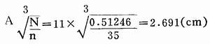
And d=3.5cm>2.691cm, so the shaft diameter is sufficient.
2. Gear transmission design
From the mechanical drawing manual, page 297, the modulus m ≥ (0.007-0.02), α = 0.7-2mm
Due to the needs of the transmission, take d = lOOmm, m = 4
Then the number of teeth Z=d/m=100/4=25
Tip height ha=m=4mm
Root height i hf=1.25m=1.25*4=5mm
Full tooth height h=2.25m=2.25*4=9mm
Tip circle diameter: da=m (2+2) -4X (25+2)= 108mm
Root diameter: df=m(2-2.5)=4*(25-2.5)=90mm
Pressure angle α=200
Transmission ratio i=1
Gear width b=40mm
3. Chain drive design
Designed by Mechanical Parts Manual Table 3.6-10
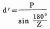
Take the chain pitch P=25.4mm; pitch circle d=lOOmm (required for transmission)
then
![]()
And in Table 3.6-11
Z=12 is relatively close, so take Z=12
Pitch diameter
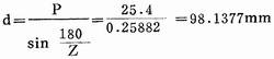
Tip circle diameter:
![]()
Root diameter:
Df=d- dr=98.1377-15.88=82.2577mm
Maximum root distance: Lx=df=82.2577mm
Maximum diameter of the flank flange:
![]()
Take dH=65mm
The tooth size is calculated as follows:
Tooth width: b=0.93b1-0.15=0.93*15.88-0.15=14.936mm
Roughness of tooth surface: r4=1.8d=1.8*15.88=28.584mm
Top side width: g=0.22d=0.22*15.88=3.4936
Root fillet: r5=1.5
4. Work roller design
The design of the work rolls is based on the principle of thin plate rolling, using a gradual theory. The center distance of the upper and lower rolls is a=lOOmm, the average pitch radius of the roller is also 100 mm, one roll (concave) groove is 5mm; the two roll convex (concave) groove is lOmm, three roll convex (concave) The groove is 12 mm, and the four-rolled roll has a circular groove of 10 mm.
The specific design dimensions are as follows:

Figure 3 Schematic diagram of the full-open barrel bucket hoop forming machine
Six, the instruction manual
1. Lubrication of the machine
This machine needs to be lubricated before use. Lubrication parts are: 1 sliding bearing at both ends of each main drive shaft; 2 gears and shaft sliding bushings of each bridge wheel; 8 meshing gears, 4 chain drive sprocket teeth and chain; 5 adjusting slider Contact gap with the rail; 6 adjust the screw and the sleeve.
When lubricating the bearing, the bushing is added to the lubricating oil along the upper oiling hole, and the machine is idling for a while before joining.
Lubricate the lubricants available on general machines.
2. Machine debugging
(1) Replace the roller to make barrel hoops of different shapes and sizes.
(2) Loosen the bolts of the feed positioning device and adjust the distance between the adjustment plates to produce strips of different widths.
(3) Rotating the upper roller to adjust the screw, changing the gap between the upper and lower rollers, rolling the strips of different thicknesses, and changing the rolling depth.
(4) Rotate the four-roller adjustment screw to change the diameter of the ferrule.
For a fixed product, do not change it after debugging. If you need to replace the product, you can debug it again.
When not in use for a long time, apply oil to the roller to prevent rust.
Seven, design summary
In terms of technology and performance, the design of the machine was successful. It has the characteristics of small size, light weight, convenient operation and flexible operation. It expands the scope of use of the original design, can be applied to similar products of various shapes, and can also change the width and thickness of the material, so the machine is widely used.
The machine is designed on the basis of the original crimping machine. The original machine has only three rollers. Before entering the roller, the bar must press the material on the punching machine to enter the roller, and the rolling and rolling are forced into one body, and the performance is extremely poor. The original roll hoop machine has a rough shape, a large volume, a large footprint, and the transmission is not extremely unstable.
This machine has been manufactured and put into production, and all performances have met the design requirements.
Eight, the main reference
1. Liu Daixiang, Shi Derang, "Handbook of Pocket Mechanical Formulas" Chongqing Publishing House, September 1st, 1st edition
2. Li Shuoben, Harbin Institute of Technology, Editor-in-Chief: Stamping Technology, Mechanical Industry Press, January 1982, 1st edition
3. "Mechanical Design Handbook" co-authored group editor: "Mechanical Design Handbook" Chemical Industry Press, 1982, 10th Beijing, 2nd Edition
4. Edited by Zhao Zhenqi: "Mechanical Drawing Manual" National Defense Industry Press, October 1986, the first edition
5. GB 325-84 "200L closed steel drum" China Standard Press, March 1985, first edition
6. Li Fuwu draws: "200L uncovering buckets, barrel hoops" product map Lanzhou barrel factory technical section January 1989
SS Nonwoven Machine,PP Spunbond Nonwoven Fabric,Melt Blown Nonwoven Fabric Making Machine,New Spunbonded Nonwoven Machine
ZHEJIANG YINFEN GROUP , http://www.yingfengmachinery.com